
Description
Product Overview
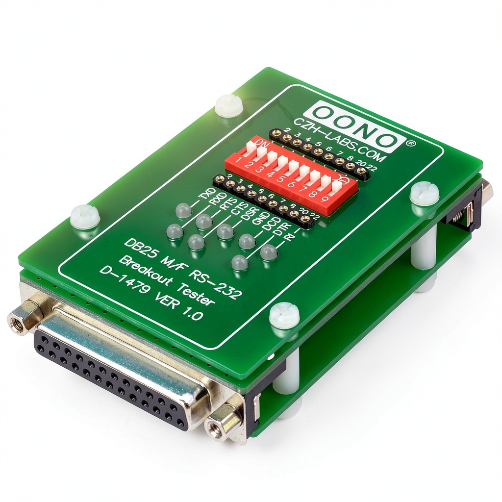
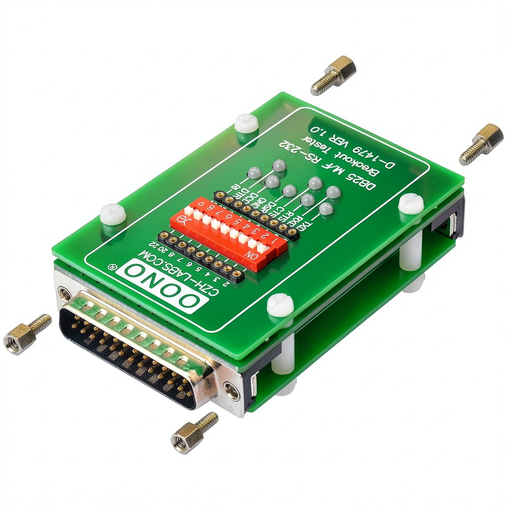
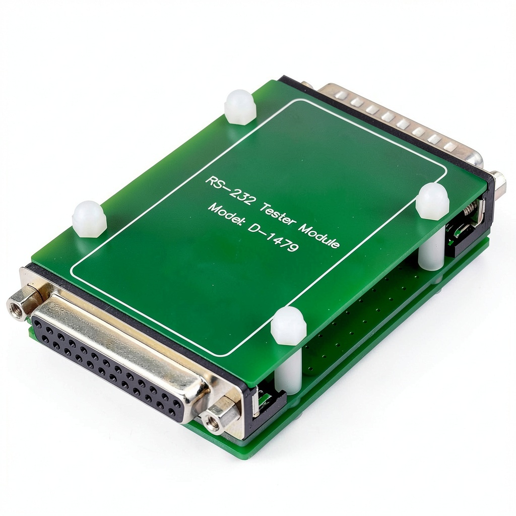
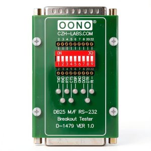
Introducing the CZH-LABS RS232 DB25 male‑to‑female breakout tester, a compact LED monitoring module designed for engineers, technicians, and hobbyists who work with serial communication interfaces. Built to meet the full RS‑232 specification, this device slots directly into a DB25 connector and instantly displays the logical state of each signal line with bright bi‑color LEDs. The rugged metal housing protects the internal circuitry while the low‑profile form factor fits into tight equipment racks and test benches. No external power source or driver is required; the tester draws power from the host interface, making it a true plug‑and‑play solution for rapid diagnostics.
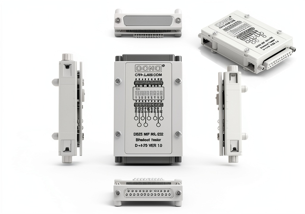
The module measures 4.69 × 3.19 × 1.26 inches and weighs only 0.01 oz, allowing it to be mounted on a standard DB25 panel without adding noticeable bulk. It features eight bi‑color LEDs that correspond to the primary RS‑232 control and data lines: DCD, RXD, TXD, DTR, DSR, RTS, CTS, and DSR. Each LED shines green for a logical HIGH and red for a logical LOW, giving an immediate visual cue of signal integrity. A built‑in DIP switch array lets the user disconnect or reconnect any individual line, facilitating isolated testing of specific pins while leaving the remaining connections untouched.
Designed for universal compatibility, the breakout tester works seamlessly with operating systems ranging from legacy Windows 98 and Windows 2000 to modern Windows 10, as well as Linux distributions and macOS 10.x. The passive nature of the device means it does not interfere with data transmission, preserving the timing and voltage levels required by the host equipment. Because it requires no external driver, the tester can be deployed in environments where software installation is restricted, such as secure laboratory networks or field service vehicles. Its simple wiring eliminates the need for an oscilloscope, reducing both equipment cost and setup time for routine checks.
Since its launch on January 25 2015, the CZH-LABS breakout tester has earned a solid reputation among professionals, reflected in a 5‑star rating from two verified customer reviews and a Best Sellers Rank of #51 within the Logic Analyzer subcategory on major e‑commerce platforms. Its compact footprint and intuitive LED display make it a favorite for troubleshooting serial links in industrial automation, embedded system development, and equipment maintenance. Whether you are verifying the direction of data flow between a computer and a peripheral device or confirming that control signals such as RTS and CTS are correctly asserted, this module provides clear, real‑time feedback that speeds up fault isolation.
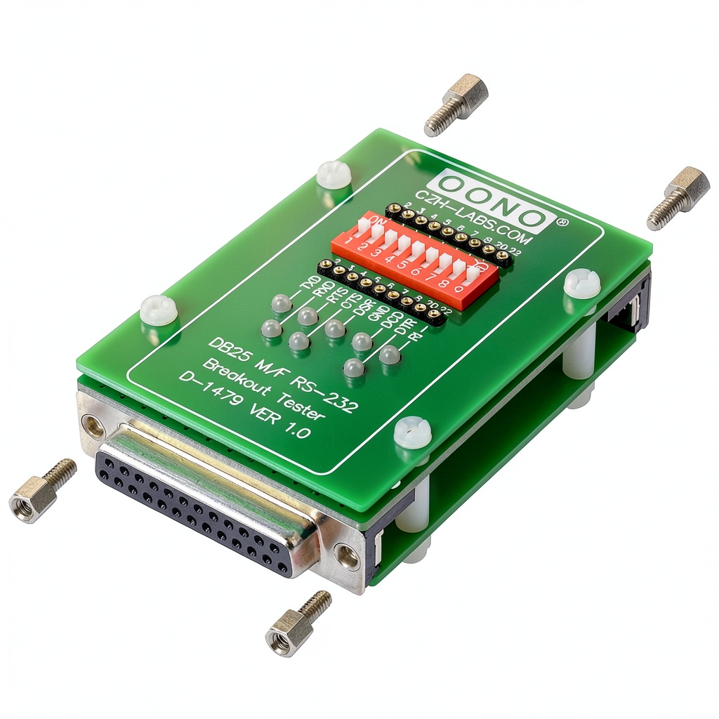
The tester’s jack sockets are equipped with removable nuts, allowing technicians to unscrew the metal shell and mate the connector with another DB25 interface if needed. This flexibility ensures that the module can be integrated into existing test rigs or custom fixtures without compromising mechanical stability. With its low cost of $21.00, the device offers an economical alternative to high‑end protocol analyzers while delivering the essential visual diagnostics required for most RS‑232 troubleshooting tasks.
The tester complies with the EIA‑232‑E standard for voltage levels, supporting -12 V to +12 V swings and a typical load of 3 kΩ. Its eight LEDs are driven directly by the RS‑232 line voltage, eliminating the need for additional transistors or opto‑isolators. The DIP switch contacts are rated for 500 mA per channel, allowing safe disconnection of high‑current control lines such as DTR and RTS. All components are RoHS‑compliant, and the unit has been tested for electromagnetic compatibility (EMC) to meet IEC 61000‑4‑3 requirements.
The enclosure is fabricated from die‑cast aluminum with a brushed finish that resists corrosion and provides excellent heat dissipation. The front panel is fitted with a clear acrylic cover that protects the LEDs from dust while allowing full visibility. The device has passed a 10,000‑cycle mechanical endurance test on the DIP switches, ensuring reliable operation even in high‑use environments such as manufacturing lines or field service trucks.
In university electronics labs, the breakout tester serves as a low‑cost alternative to expensive logic analyzers. Students can connect the module to a microcontroller development board and observe the LED patterns as the board transmits UART data. By toggling the DIP switches, they can simulate fault conditions such as a stuck‑low DTR line and immediately see the impact on the LED display, reinforcing theoretical concepts with practical observation.
For industrial automation engineers, the tester simplifies the validation of PLC communication links. By inserting the module between a PLC’s RS‑232 port and a supervisory computer, the engineer can verify that control signals such as RTS and CTS are correctly asserted during handshaking sequences. The ability to isolate individual lines with the DIP switches also aids in diagnosing intermittent faults caused by noisy environments or connector wear.
Field technicians often encounter intermittent serial failures that are difficult to capture with software tools alone. The visual nature of the LED indicators allows a quick visual scan to pinpoint whether a line is stuck at a constant level or toggling erratically. By setting the DIP switch to disconnect a suspect line, the technician can confirm whether the fault resides in the cable, the device, or the host controller, dramatically reducing mean‑time‑to‑repair (MTTR).
The typical testing workflow begins by inserting the breakout tester into the DB25 port of the device under test, then connecting the opposite end to the host computer. Once powered, the LEDs immediately reflect the idle state of each line. By toggling the DIP switches, the user can force a line low or high, verifying that the host correctly detects the change. This method eliminates the need for a separate signal generator and provides a clear visual reference for both novice and experienced engineers.
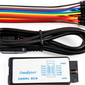
For advanced diagnostics, the tester can be combined with a logic analyzer or a protocol decoder to capture timing information while the LEDs provide a real‑time visual cue. This hybrid approach enables engineers to pinpoint subtle issues such as jitter, line‑level noise, or improper handshaking that may not be evident from LED observation alone.
Operators should ensure that the RS‑232 port is powered off before inserting or removing the tester to prevent accidental short circuits. When the device is powered, avoid touching the metal contacts with conductive objects. The module is rated for indoor use only and should not be exposed to moisture or extreme temperatures beyond the specified operating range of 0 °C to 50 °C.
![[Product front view showing all components]](https://www.warmshop.store/wp-content/uploads/2026/07/c39037f57f564389b0457f138eefc644.jpg)
Usage
In a typical laboratory setup, the breakout tester can be placed between a computer’s serial port and a peripheral device such as a barcode scanner, PLC, or legacy instrumentation. By observing the LED colors on the DCD, TXD, and RXD lines, engineers can instantly confirm whether data is being transmitted and received correctly. The bi‑color display also helps identify idle or error states; a steady red LED indicates a low signal, while a flashing green LED shows activity on the line.
In field service scenarios, the module’s plug‑and‑play nature eliminates the need to carry bulky test equipment. A technician can quickly attach the tester to a machine’s DB25 port, glance at the LEDs, and determine if a communication fault lies in the wiring, the host controller, or the peripheral device. The DIP switch array enables selective isolation of a single line, allowing the user to inject a known state and observe the response without disrupting the rest of the system.
For university electronics labs, the breakout tester serves as a low‑cost alternative to expensive logic analyzers. Students can connect the module to a microcontroller development board and observe the LED patterns as the board transmits UART data. By toggling the DIP switches, they can simulate fault conditions such as a stuck‑low DTR line and immediately see the impact on the LED display, reinforcing theoretical concepts with practical observation.
For industrial automation engineers, the tester simplifies the validation of PLC communication links. By inserting the module between a PLC’s RS‑232 port and a supervisory computer, the engineer can verify that control signals such as RTS and CTS are correctly asserted during handshaking sequences. The ability to isolate individual lines with the DIP switches also aids in diagnosing intermittent faults caused by noisy environments or connector wear.
Field technicians often encounter intermittent serial failures that are difficult to capture with software tools alone. The visual nature of the LED indicators allows a quick visual scan to pinpoint whether a line is stuck at a constant level or toggling erratically. By setting the DIP switch to disconnect a suspect line, the technician can confirm whether the fault resides in the cable, the device, or the host controller, dramatically reducing mean‑time‑to‑repair (MTTR).
The typical testing workflow begins by inserting the breakout tester into the DB25 port of the device under test, then connecting the opposite end to the host computer. Once powered, the LEDs immediately reflect the idle state of each line. By toggling the DIP switches, the user can force a line low or high, verifying that the host correctly detects the change. This method eliminates the need for a separate signal generator and provides a clear visual reference for both novice and experienced engineers.
For advanced diagnostics, the tester can be combined with a logic analyzer or a protocol decoder to capture timing information while the LEDs provide a real‑time visual cue. This hybrid approach enables engineers to pinpoint subtle issues such as jitter, line‑level noise, or improper handshaking that may not be evident from LED observation alone.
Operators should ensure that the RS‑232 port is powered off before inserting or removing the tester to prevent accidental short circuits. When the device is powered, avoid touching the metal contacts with conductive objects. The module is rated for indoor use only and should not be exposed to moisture or extreme temperatures beyond the specified operating range of 0 °C to 50 °C.
Why Choose Us
CZH‑LABS has a long history of delivering reliable test equipment for industrial and scientific applications. Each breakout tester is manufactured under strict quality‑control procedures, including component screening, solder joint inspection, and functional testing on a simulated RS‑232 data stream. The use of a metal enclosure not only provides electromagnetic shielding but also ensures durability in harsh environments where temperature fluctuations and vibration are common. Our commitment to customer support includes a one‑year limited warranty and responsive technical assistance via email and phone.
Our manufacturing process includes a 100% functional test on a simulated RS‑232 data stream before each unit leaves the factory. Units that fail any parameter are reworked or discarded, ensuring that every customer receives a fully operational tester. In addition, we maintain a traceable component database, allowing us to quickly identify and replace any part that may be subject to recall or performance issues.
Customers benefit from a dedicated support line staffed by engineers familiar with RS‑232 testing. Our response time goal is under 24 hours for standard inquiries, and we provide detailed troubleshooting guides that cover common issues such as LED mis‑interpretation, DIP switch configuration, and connector compatibility. The one‑year limited warranty covers defects in materials and workmanship, and we offer optional extended service contracts for organizations that require longer coverage.
CZH‑LABS maintains regional service centers in North America, Europe, and Asia‑Pacific, ensuring that customers receive prompt technical assistance and spare parts. Our online portal provides access to downloadable resources, firmware updates, and a community forum where users can share testing strategies and solutions.
For OEM partners, we offer customization services such as branding the front panel, adding extra DIP switches, or integrating a microcontroller for advanced diagnostics. These options allow manufacturers to embed the breakout tester into larger test systems or to provide a branded accessory that aligns with their product line.
CZH‑LABS is committed to sustainable manufacturing practices, utilizing recycled aluminum for the enclosure and minimizing packaging waste by shipping the tester in a reusable foam insert. Our environmental policy aligns with ISO 14001 standards, and we regularly audit our supply chain to ensure compliance with ecological and social responsibility criteria.
The modular design of the breakout tester allows for future upgrades, such as adding additional LED colors or integrating a small microcontroller for protocol decoding. This forward‑compatible architecture ensures that the investment remains valuable as serial communication standards evolve.
Key Features
- Bi‑color LEDs give instant visual feedback of HIGH (green) and LOW (red) states for all eight RS‑232 lines.
- Plug‑and‑play design requires no external power or driver, simplifying setup and reducing cost.
- Removable jack socket nuts allow easy mating with other DB25 connectors or custom test rigs.
- Built‑in DIP switch array enables selective isolation or reconnection of individual signal lines for targeted diagnostics.
- One‑year limited warranty and dedicated technical support ensure reliable long‑term operation.
FAQ
Can the tester be used with USB‑to‑Serial adapters?
Yes, the module draws power from the RS‑232 signals, so it works with any adapter that presents a standard DB25 pinout, including USB‑to‑Serial converters.
Do I need to install any software to see the LED status?
No software is required; the LEDs operate independently of the host computer and provide real‑time visual indication of signal levels.
What is the maximum data rate the tester can handle?
The breakout tester follows the RS‑232 electrical specifications and can monitor signals up to 115 kbps, which covers the majority of serial communication applications.






















Reviews
There are no reviews yet.